TRI-PHASEI-TECHAutomation Solutions of WI
Why Choose Steel Cable Tray for Global Projects?

Why Choose Steel Cable Tray for Global Projects?

Global infrastructure rarely follows one climate, one code, or one installation habit. A cable route may cross a humid port, a dusty factory, and a cold logistics hub. Steel Cable Tray offers a practical foundation for these demanding transitions. Its rigid structure supports power, control, and communication cables across long corridors. Properly selected systems can resist impact, maintain spacing, and simplify inspection. They also create visible routes that technicians can understand quickly. That matters during commissioning and future maintenance. Small details matter. Engineers should check load, span, corrosion exposure, cable fill, and access before approval. Galvanized steel may suit indoor or moderate environments. Hot-dip galvanizing or specialized coatings may better serve aggressive atmospheres. The right answer depends on evidence, not habit.

International projects also require disciplined documentation. Product data should identify material grade, coating thickness, load capacity, joint design, and testing methods. References to IEC 61537 or NEMA VE 1 can support evaluation. However, local requirements still deserve careful review. Experienced installers know that drawings rarely show every field condition. A tray may meet the specification and still clash with a sprinkler pipe or maintenance walkway. That is where site verification becomes valuable. It is not flawless. Steel can add weight and require careful lifting plans. It can also corrode when protection is poorly matched. Ignoring these limits weakens an otherwise sound design. Yet, with competent selection, verified manufacturing, and clear installation records, Steel Cable Tray can provide a dependable route for global projects. Its value is not just strength. It is predictable performance over time.

Why Choose Steel Cable Tray for Global Projects?

What Is a Steel Cable Tray?

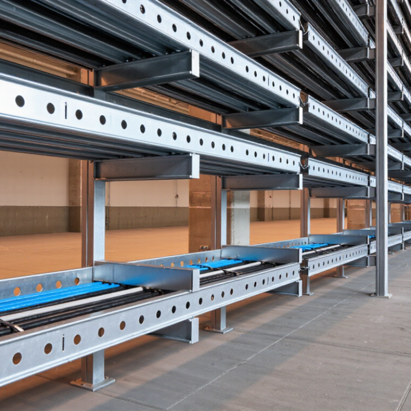
A steel cable tray is a support system for electrical and communication cables. It usually consists of galvanized or coated steel sections, joined to form a continuous route. Unlike a closed conduit, a tray leaves the cables visible and accessible. This open structure improves ventilation and makes inspection easier.

In global projects, steel trays are selected for their strength, fire resistance, and consistent performance in industrial environments. They can carry heavy cable bundles across factories, tunnels, power facilities, and commercial buildings. Engineers normally check load capacity, span length, corrosion exposure, grounding, and local installation requirements. A properly designed tray also reduces sharp bends, helping installers protect cable insulation.

Details matter.

During site inspections, I have seen trays installed with weak supports or crowded cables. The material was suitable, but the installation was not. That mistake can increase heat, complicate maintenance, and shorten service life. Designers should allow room for future cables without creating unnecessary oversizing. Galvanized steel performs well in many conditions, yet coastal or chemical areas may require stronger corrosion protection. Standards such as IEC or NEMA guidance can support selection, but local codes and project specifications still control the final design. A steel cable tray is not merely a metal shelf; it is part of the project’s long-term cable management and safety system.

Why Choose Steel Cable Tray for Global Projects?

Steel cable trays are widely selected for industrial and infrastructure installations because steel combines high structural strength, predictable performance, and compatibility with protective coatings. The chart compares representative physical properties of commonly used tray materials.

Values are representative room-temperature properties for commonly used material grades: low-carbon structural steel, stainless steel, and 6061-T6 aluminum. Actual cable-tray performance depends on thickness, perforation, span, support spacing, coating system, temperature, and project-specific loading requirements.

How Steel Cable Trays Support Global Infrastructure Projects

Global infrastructure is becoming more distributed, and cable routes must cross substations, tunnels, ports, and data facilities. The IEA’s Electricity Grids and Secure Energy Transitions (2023) estimates that 80 million kilometres of grids must be added or refurbished by 2040. It also says annual grid investment should exceed $600 billion by 2030. These figures make cable support a project-control issue, not a minor accessory.

Steel cable trays help standardise long routes across different countries. Their mechanical strength supports heavy power and control cables over longer spans, reducing additional hangers. When properly bonded, they can support electrical continuity under IEC 61537 requirements. Engineers still need to check seismic loads, thermal expansion, corrosion classes, and local fire rules. Steel is not automatically the best answer. Not always.

IRENA’s World Energy Transitions Outlook 2024 calls for about 11.2 terawatts of renewable capacity by 2030. More generation means denser, more exposed cable networks. Hot coastal air, salt spray, dust, and rushed installation can shorten service life. Galvanized or coated steel must match the environment, fasteners, and cut-edge treatment. A strong tray with weak accessories is still a weak system. Global projects benefit from familiar fabrication methods and clear inspection points. Teams can verify load class, support spacing, bonding, and coating thickness before energization. Drawings are never perfect. They are not.

Key Benefits of Steel Cable Tray Systems

Why Choose Steel Cable Tray for Global Projects?

Key Benefits of Steel Cable Tray Systems

Steel cable tray systems provide a practical route for power, control, and communication cables. Their open structure improves airflow and makes inspection easier than enclosed conduits. On active construction sites, technicians can identify damaged cables quickly. That matters when shutdowns are expensive.

Steel offers strong mechanical support across long spans. A properly selected tray can carry heavy cable groups while resisting vibration and accidental impact. Galvanized steel performs well in many indoor and outdoor environments. Stainless steel is more suitable for coastal areas, chemical exposure, or persistent moisture. The right finish matters. A poor coating choice can create corrosion problems within a few years.

Installation is also flexible. Workers can cut sections, add bends, and extend routes as equipment changes. This reduces future disruption, although careless cutting may weaken protective finishes. Grounding and bonding must be checked at every connection. Local electrical codes and project specifications should guide the design, not habit alone. Load calculations, support spacing, thermal conditions, and seismic requirements need documented review. In my experience, small planning errors often appear later as sagging trays or crowded cables. Steel cable tray is reliable, but it is not automatically maintenance-free. Regular inspections still matter.

How to Select Steel Cable Trays for Different Environments

Why Choose Steel Cable Tray for Global Projects?

How to Select Steel Cable Trays for Different Environments

Selecting a steel cable tray starts with the installation environment, not the catalog image. Indoor electrical rooms usually need standard galvanized steel for organized, ventilated cable routing. It is strong, familiar, and easy to inspect. Outdoor projects demand better protection. Hot-dip galvanized steel resists rain, dust, and temperature changes more effectively. Coastal sites require extra caution because salt air can attack exposed metal quickly.

Chemical plants and wastewater facilities may need stainless steel or specialized protective coatings. Check the coating thickness, drainage design, and compatibility with nearby chemicals. Do not select a tray by width alone. Calculate cable weight, support spacing, expansion movement, and future capacity. A tray that looks generous today may become crowded after one expansion.

Site experience matters here. I have seen trays installed correctly but supported too far apart, causing visible deflection. That mistake is easy to miss during delivery. Seismic regions need reinforced supports and properly designed connectors. Areas with high heat require attention to cable temperature and ventilation. Fire-rated routes may require a tested system, not simply thicker steel. Project teams should also review local standards, grounding methods, and installation skills before approval. The cheapest option can become expensive when corrosion appears early or maintenance access is poor. There is no universal tray choice. Surface conditions, load data, climate, and inspection habits must guide the decision.

Installation Standards, Safety, and Long-Term Maintenance

Steel cable tray suits global projects because it combines high load capacity with accessible routing. Installation must follow IEC 61537 and the adopted national electrical code. These standards address mechanical strength, corrosion resistance, bonding, and safe separation. Support spacing should match the tested load, not a convenient drawing dimension. A crowded tray can deform, block heat dissipation, and complicate future testing.

Safety deserves equal attention. NFPA’s Home Structure Fires report found that electrical distribution and lighting equipment caused about 35,150 home fires annually in the United States from 2015 to 2019. Those fires caused approximately 470 deaths, 1,100 injuries, and 1.3 billion dollars in direct property damage. Cable tray cannot prevent every electrical failure. Proper conductor sizing, grounding continuity, fire stopping, and clear working space remain essential. Never use the tray as a walkway. It sounds obvious, yet field inspections still find damaged covers and unsupported cables.

Long-term maintenance should follow documented risk assessments and the inspection guidance in NEMA VE 2. Check for loose connections, sharp edges, corrosion, overloaded sections, and missing bonding jumpers. Inspect after major construction work, flooding, or vibration events. IEA’s Electricity 2024 report projects global electricity demand to grow by about 3.3% annually from 2024 to 2026. That growth may increase tray loading over time. A weakness in many projects is poor recordkeeping. As-built drawings, torque records, and photographs should be updated after every modification, even when the change appears minor.

Why Choose Steel Cable Tray for Global Projects? - Installation Standards, Safety, and Long-Term Maintenance
Evaluation Dimension Applicable Standard or Reference Verified Requirement or Technical Data Global Project Value
International Product Qualification IEC 61537
EN 61537
IEC 61537 specifies requirements and tests for cable tray systems and cable ladder systems used for the support, accommodation, and possibly segregation of cables. A tray system evaluated against IEC 61537 provides a common technical basis for performance comparison across international projects. The project specification should identify the adopted edition and any local deviations.
North American Compliance NEMA VE 1
NFPA 70, NEC Article 392
NEMA VE 1 addresses metallic cable tray systems, including construction, dimensions, and performance testing. NEC Article 392 covers cable-tray installation, permitted wiring methods, ampacity, support, grounding, and bonding requirements. Projects in the United States and other jurisdictions referencing NEC should coordinate tray selection with the electrical design, cable type, conductor arrangement, environmental conditions, and authority having jurisdiction.
Load Capacity and Deflection IEC 61537
NEMA VE 1
Approved project calculations
The allowable cable load depends on tray width, material, side-rail height, rung or bottom configuration, support span, splice location, and installation environment. There is no single universal load rating for all steel trays; the tested or calculated rating must be used. Steel provides high stiffness and predictable structural behavior, but the selected span and load class must match the manufacturer’s tested data or engineered calculations. Do not use a catalog load rating outside its stated support-span conditions.
Support Spacing and Installation IEC 61537
NEMA VE 1
Project installation specification
Supports must be designed for the tray self-weight, cable weight, accessories, environmental loads, and installation loads. Additional supports are normally required near changes in direction, junctions, vertical transitions, and splice connections when required by the tested system or project design. Using a standardized support layout reduces deflection, protects cable insulation, and simplifies inspection. Actual support spacing must follow the approved design and the tray system’s load-versus-span data rather than a generic spacing assumption.
Grounding and Bonding NFPA 70, NEC Article 392
IEC 60364 series
Local electrical regulations
Metallic tray sections, fittings, and discontinuities must be electrically continuous and bonded as required by the governing electrical code. Where a cable tray is used as an equipment grounding conductor, the applicable code conditions, identification, continuity, and cross-sectional requirements must be satisfied. Steel tray can form part of a coordinated bonding system when permitted by the local code and correctly installed. Bonding jumpers, expansion joints, painted surfaces, and transitions between dissimilar materials require specific design review.
Corrosion Protection ISO 1461
ISO 12944
Project environmental classification
For hot-dip galvanized fabricated steel, ISO 1461 gives minimum coating-thickness requirements based on steel thickness. For example, fabricated steel thicker than 6 mm requires an average coating thickness of at least 85 μm and a local minimum of 70 μm. Coating selection should reflect humidity, salt exposure, chemicals, temperature, and expected service life. In marine or chemically aggressive areas, a higher-grade coating system or stainless steel may be justified after an ISO 12944-based corrosion assessment.
Cut-Edge and Field Modification Control ISO 1461
Approved coating-repair procedure
Field-cut, drilled, or damaged galvanized surfaces require compatible repair treatment in accordance with the approved coating-repair procedure. Burrs and sharp edges should be removed before cables are installed. Proper repair of modified areas limits localized corrosion and reduces the risk of cable-jacket damage. All field modifications should be recorded and inspected before cable pulling.
Cable Separation and Heat Management NFPA 70, NEC Article 392
IEC 60364 series
Cable manufacturer data
Power, control, instrumentation, communication, and fire-alarm cables may require separation, barriers, or dedicated tray systems according to the governing code, electromagnetic-compatibility design, and cable manufacturer instructions. Cable ampacity must account for grouping and installation conditions. Steel tray supports organized routing and can improve inspection access, but it does not automatically eliminate electromagnetic interference or thermal derating. Cable grouping and separation must be verified during design and commissioning.
Mechanical and Personnel Safety IEC 61537
Applicable occupational-safety regulations
Tray edges, covers, fittings, and supports should not create unacceptable cutting, snagging, falling-object, or access hazards. Covers, barriers, and mechanical protection are required where the installation risk assessment or local regulations identifies exposure to impact, falling materials, or unauthorized access. A rigid steel system provides robust support in industrial environments, but it must not be used as a walkway or working platform unless specifically designed and approved for that purpose. Safe access routes and overhead protection should be addressed separately.
Inspection and Commissioning Approved inspection and test plan
Local electrical code
Inspection should verify tray alignment, support spacing, fastener tightness, splice installation, coating condition, bonding continuity, cable fill, bend radius, separation, and the absence of sharp edges or unauthorized modifications. A documented inspection process creates a consistent handover record for multinational teams and provides baseline information for future maintenance, extensions, and fault investigations.
Long-Term Maintenance Owner maintenance plan
Environmental corrosion assessment
Periodic inspections should check corrosion, loose or missing hardware, damaged covers, overloaded sections, cable sag, water accumulation, blocked drainage, coating damage, and bonding continuity. Inspection intervals should be risk-based and shortened in corrosive or high-vibration areas. Steel cable trays are durable and repairable, but long service life depends on keeping drainage paths clear, correcting coating damage promptly, controlling unauthorized cable additions, and maintaining an accurate cable-route register.
Lifecycle and Sustainability Project environmental requirements
Applicable waste and recycling regulations
Steel is a recyclable material, and damaged or redundant tray sections can generally be segregated for metal recycling. Lifecycle evaluation should include manufacturing, galvanizing or coating, transport, installation, maintenance, replacement, and end-of-life handling. Standardized steel components can support phased expansion and component replacement. Sustainability claims should be based on project-specific environmental data rather than material selection alone.